-
Get involved.
We want your input!
Apply for Membership and join the conversations about everything related to broadcasting.
After we receive your registration, a moderator will review it. After your registration is approved, you will be permitted to post.
If you use a disposable or false email address, your registration will be rejected.
After your membership is approved, please take a minute to tell us a little bit about yourself.
https://www.radiodiscussions.com/forums/introduce-yourself.1088/
Thanks in advance and have fun!
RadioDiscussions Administrators
You are using an out of date browser. It may not display this or other websites correctly.
You should upgrade or use an alternative browser.
You should upgrade or use an alternative browser.
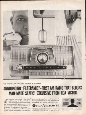
RCA Victor - Automatic Filteramic
- Thread starter amfmsw
- Start date
Well, for anyone interested in better American radios, this is all I've ever found on the "Filteramic"
The first ever radio to block manmade static. http://www.goantiques.com/scripts/images,id,561630.html
The first ever radio to block manmade static. http://www.goantiques.com/scripts/images,id,561630.html
I've been looking and hadn't found anything.
It's probably not a noise blanking circuit unless they give you a switch to turn it on and off.
Even if "automatic", these circuits all detract from the best sound, so it would have to be very good to satisfy RCA.
Only other thing that could help with local noises is loop antenna/bridge magic. Does the loop seem unusual in any way?
On AM, many noises ride in stright through the power supply since these 5 tube 117 v heater string radios had
no power transformer. Most likely this was an R-C network input filter on the incoming AC that was somewhat effective with AC line noises.
But what ever produced the noise also radiated some beside putting noise on the line.
They helped somewhat. Should have been there all the time, but the All-American 5 radio had achieved truest parts minimization
by cost competition by 1959. Some radios had only a simple bypass cap on on side of the line.
RCA may have used 2 caps and an inductor for a much better filter.
A close friend who worked at the Sarnoff Labs once spoke about about a circuit they were thinking about for radio receivers in the 60s. The way he explained it was that it contained two unique circuits.
One circuit was sort of a reverse AGC, that would allow highs to pass during full modulation. When there was low modulation, a curve would be introduced into the audio to roll down the highs thus masking the noise to some degree. This "invention" later evolved into what we know in automotive car radios as DNR.
But their second trick was to have a second stationary receiver in the radio that would receive just outside the AM band. The thought was to introduce a second signal with the received audio 180 degrees out of phase with the radio station signal. Presuming that noise would likely be the same on 1650 as it is on 1000, there would be a cancellation of sorts. It worked OK, but the down side of it was that it added $13 to the cost of manufacturing of the radio, and the car companies nixed it. Thus the idea died.
I had an opportunity to hear one of these radios, which were designed before NRSC was every thought of. It was very good. And when a light switch or something else would turn on, it would suppress the pop or the buzz by 9 dB or more, making the station you were listening to sound much better.
When I was a teenager, I worked in the radio/TV repair department for a big department store (Webb's City in St. Petersburg, FL) and several RCA "Filteramic" radios came across my workbench. On disassembly, I noticed an unusual-looking "loop-stick" type antenna. I was a good service technician and knew basic circuit theory but was puzzled. Now I'm an accomplished electronic circuit design engineer. Recently, on an on-line electronics engineering forum, the topic was electro-magnetic wave propagation and the discussion triggered a memory of that Filteramic antenna. Now I understand how it works. Bear with me as I explain a bit of underlying theory.
Electromagnetic or "radio" waves travel through space as one but, as the name implies, there's both a magnetic field and an electric field component. Each can be easily "received" but by antennas that are quite different. For example, most car radios use a "whip" antenna, which responds only to the electric field, while most table and portable radios use an inductor (a coil consisting of many turns of wire). Sometimes these coils are a flat spiral winding on the inside of the radio's back cover but often the coil is wound on a 3 to 12-inch long powdered-iron rod called a "loop-stick" antenna. Regardless of their form, these coils respond almost exclusively to the magnetic field. None of this is unusual.
But the Filteramic loop-stick is unusual. Surrounding the coil and rod of the loop-stick is what appears to be just a gray plastic tube. But the plastic is actually electrically conductive, allowing it to function as a Faraday shield to stop even the slightest response to an electric field. This is the key to its performance! Household appliances like shavers, food mixers, and sewing machines typically use small "brush-type" electric motors that create tiny sparks as they spin. These sparks unintentionally create radio-frequency interference in the form of electric field waves. So the shielding plastic tube prevents the antenna from picking up the noisy interference, which is typically heard as a "buzzing" or "whining" sound that depends on the speed of the motor. This kind of interference is commonly generated by vacuum-cleaners, fluorescent lights, and many power tools, too.
What amazed me most in this story is that I actually remembered RCA's coined word for this innovation, "Filteramic," after 60 years! But the internet search not only found the ad copy but this forum as well! I'm now semi-retired from a long career in electronics engineering, including as head of electronics at Capitol Records from 1981 to 1988. And I restore classic radios as a hobby!
Bill Whitlock
Life Fellow of the Audio Engineering Society
Life Senior Member of the Institute for Electrical and Electronic Engineers
Ventura, California
Attachments
Interesting read, @Bill Whitlock and welcome to Radio Discussions! Hopefully you'll find other topics and discussions here to comment and offer insight on!
As far as the radio in the ad in your post, which is also in the link in amfmsw's earlier post, I'm nearly certain my grandmother had that exact radio. Both of my last living grandparents passed in the 80s and it's amazing the stuff, especially electronics, that we tossed out as being old and antiquated. Much of it was donated to Goodwill or to charitable organizations for their rummage sales. Hopefully someone more appreciative than we were at the time, made a good home for it.
As far as the radio in the ad in your post, which is also in the link in amfmsw's earlier post, I'm nearly certain my grandmother had that exact radio. Both of my last living grandparents passed in the 80s and it's amazing the stuff, especially electronics, that we tossed out as being old and antiquated. Much of it was donated to Goodwill or to charitable organizations for their rummage sales. Hopefully someone more appreciative than we were at the time, made a good home for it.
Last edited:
HeWhen I was a teenager, I worked in the radio/TV repair department for a big department store (Webb's City in St. Petersburg, FL) and several RCA "Filteramic" radios came across my workbench. On disassembly, I noticed an unusual-looking "loop-stick" type antenna. I was a good service technician and knew basic circuit theory but was puzzled. Now I'm an accomplished electronic circuit design engineer. Recently, on an on-line electronics engineering forum, the topic was electro-magnetic wave propagation and the discussion triggered a memory of that Filteramic antenna. Now I understand how it works. Bear with me as I explain a bit of underlying theory.
Electromagnetic or "radio" waves travel through space as one but, as the name implies, there's both a magnetic field and an electric field component. Each can be easily "received" but by antennas that are quite different. For example, most car radios use a "whip" antenna, which responds only to the electric field, while most table and portable radios use an inductor (a coil consisting of many turns of wire). Sometimes these coils are a flat spiral winding on the inside of the radio's back cover but often the coil is wound on a 3 to 12-inch long powdered-iron rod called a "loop-stick" antenna. Regardless of their form, these coils respond almost exclusively to the magnetic field. None of this is unusual.
But the Filteramic loop-stick is unusual. Surrounding the coil and rod of the loop-stick is what appears to be just a gray plastic tube. But the plastic is actually electrically conductive, allowing it to function as a Faraday shield to stop even the slightest response to an electric field. This is the key to its performance! Household appliances like shavers, food mixers, and sewing machines typically use small "brush-type" electric motors that create tiny sparks as they spin. These sparks unintentionally create radio-frequency interference in the form of electric field waves. So the shielding plastic tube prevents the antenna from picking up the noisy interference, which is typically heard as a "buzzing" or "whining" sound that depends on the speed of the motor. This kind of interference is commonly generated by vacuum-cleaners, fluorescent lights, and many power tools, too.
What amazed me most in this story is that I actually remembered RCA's coined word for this innovation, "Filteramic," after 60 years! But the internet search not only found the ad copy but this forum as well! I'm now semi-retired from a long career in electronics engineering, including as head of electronics at Capitol Records from 1981 to 1988. And I restore classic radios as a hobby!
Bill Whitlock
Life Fellow of the Audio Engineering Society
Life Senior Member of the Institute for Electrical and Electronic Engineers
Ventura, California
Thank you so much for the explanation! I bought one of these radios recently and I haven't been able to find anything on how they actually worked.When I was a teenager, I worked in the radio/TV repair department for a big department store (Webb's City in St. Petersburg, FL) and several RCA "Filteramic" radios came across my workbench. On disassembly, I noticed an unusual-looking "loop-stick" type antenna. I was a good service technician and knew basic circuit theory but was puzzled. Now I'm an accomplished electronic circuit design engineer. Recently, on an on-line electronics engineering forum, the topic was electro-magnetic wave propagation and the discussion triggered a memory of that Filteramic antenna. Now I understand how it works. Bear with me as I explain a bit of underlying theory.
Electromagnetic or "radio" waves travel through space as one but, as the name implies, there's both a magnetic field and an electric field component. Each can be easily "received" but by antennas that are quite different. For example, most car radios use a "whip" antenna, which responds only to the electric field, while most table and portable radios use an inductor (a coil consisting of many turns of wire). Sometimes these coils are a flat spiral winding on the inside of the radio's back cover but often the coil is wound on a 3 to 12-inch long powdered-iron rod called a "loop-stick" antenna. Regardless of their form, these coils respond almost exclusively to the magnetic field. None of this is unusual.
But the Filteramic loop-stick is unusual. Surrounding the coil and rod of the loop-stick is what appears to be just a gray plastic tube. But the plastic is actually electrically conductive, allowing it to function as a Faraday shield to stop even the slightest response to an electric field. This is the key to its performance! Household appliances like shavers, food mixers, and sewing machines typically use small "brush-type" electric motors that create tiny sparks as they spin. These sparks unintentionally create radio-frequency interference in the form of electric field waves. So the shielding plastic tube prevents the antenna from picking up the noisy interference, which is typically heard as a "buzzing" or "whining" sound that depends on the speed of the motor. This kind of interference is commonly generated by vacuum-cleaners, fluorescent lights, and many power tools, too.
What amazed me most in this story is that I actually remembered RCA's coined word for this innovation, "Filteramic," after 60 years! But the internet search not only found the ad copy but this forum as well! I'm now semi-retired from a long career in electronics engineering, including as head of electronics at Capitol Records from 1981 to 1988. And I restore classic radios as a hobby!
Bill Whitlock
Life Fellow of the Audio Engineering Society
Life Senior Member of the Institute for Electrical and Electronic Engineers
Ventura, California
K
kenglish
Guest
Sounds like the idea behind the McKay-Dymek DA-5, and that Ramsey Magnetic antenna we all used for EAS monitoring.
One circuit was sort of a reverse AGC, that would allow highs to pass during full modulation. When there was low modulation, a curve would be introduced into the audio to roll down the highs thus masking the noise to some degree. This "invention" later evolved into what we know in automotive car radios as DNR.
Is that related to National Semiconductor's "DNR" (Dynamic Noise Reduction) that was used in a lot of car cassette players? Fujitsu (I think Fujitsu made them, anyways) also used it in the Propac series of 1 2/5 IPS cassette machines sold by AEI/DMX Music (and by Muzak as the CP2500).
- Status
- This thread has been closed due to inactivity. You can create a new thread to discuss this topic.