-
Get involved.
We want your input!
Apply for Membership and join the conversations about everything related to broadcasting.
After we receive your registration, a moderator will review it. After your registration is approved, you will be permitted to post.
If you use a disposable or false email address, your registration will be rejected.
After your membership is approved, please take a minute to tell us a little bit about yourself.
https://www.radiodiscussions.com/forums/introduce-yourself.1088/
Thanks in advance and have fun!
RadioDiscussions Administrators
You are using an out of date browser. It may not display this or other websites correctly.
You should upgrade or use an alternative browser.
You should upgrade or use an alternative browser.
YOUR THOUGHTS ON THIS ATU
- Thread starter Radio Bob
- Start date
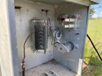
Copper strap is generally used for RF connections because it has more surface area and therefore, lower loss.
Agreed. I have never seen this kind of a hookup with wire beforeCopper strap is generally used for RF connections because it has more surface area and therefore, lower loss.
Looks like some kind of braiding done with #12 wire?
Reminds me of Litz wire.
There was a 4-tower phasor in Simi Valley wired with #10 solid wire. Didn't perform well at all.
Reminds me of Litz wire.
There was a 4-tower phasor in Simi Valley wired with #10 solid wire. Didn't perform well at all.
Better be careful messing around in this thing. It was tuned up built with materials the way it is. If you start changing materials, distance from the side of the cabinet or length of jumpers, you might have to stick a bridge on it to see if you altered resistance or reactance as seen toward the common point.I've never seen hookup wire used before either. I plan to replace that with a strap also add a static coil across the line coming in
Radio Bob, is this system malfunctioning? Is this completely your project to engineer? I agree with Kelly A, don't make changes unless you have an impedance bridge and are comfortable with what could happen as things are changed.
How is antenna current measured in this system? Is this a directional antenna system or a non-directional? Is the tower base insulated or is this driving a folded-unipole feed system? Anything else crossing the tower base? Is the antenna load inductive or capacitive? And.... is that wire going to ground at the output jumper closely spaced to the strap to act as a spark gap?
How is antenna current measured in this system? Is this a directional antenna system or a non-directional? Is the tower base insulated or is this driving a folded-unipole feed system? Anything else crossing the tower base? Is the antenna load inductive or capacitive? And.... is that wire going to ground at the output jumper closely spaced to the strap to act as a spark gap?
Last edited:
I am aware that a bridge must be used to retune the network once changes are made. The antenna is a folded unipole with grounded tower no bae insulator. There is an FM antenna also on the tower. Yes that piece of wire is a gap for lightening. The transmitter has sustained major damage twice in the past years and I am going to add a standard gap and also a static choke. This station is nondirectional. After any changes I'll Then retune it with a bridge. I was asking for advice as I have never seen copper wire used in a tuning unit before. The station uses the indirect method to determine antenna current. Thanks for the advice.Radio Bob, is this system malfunctioning? Is this completely your project to engineer? I agree with Kelly A, don't make changes unless you have an impedance bridge and are comfortable with what could happen as things are changed.
How is antenna current measured in this system? Is this a directional antenna system or a non-directional? Is the tower base insulated or is this driving a folded-unipole feed system? Anything else crossing the tower base? Is the antenna load inductive or capacitive? And.... is that wire going to ground at the output jumper closely spaced to the strap to act as a spark gap?
In other words, high impedance.I am aware that a bridge must be used to retune the network once changes are made. The antenna is a folded unipole with grounded tower no bae insulator.
Not sure what you mean by standard gap. There are the typical acorn-nut gaps and the more modern horn gaps.There is an FM antenna also on the tower. Yes that piece of wire is a gap for lightening. The transmitter has sustained major damage twice in the past years and I am going to add a standard gap and also a static choke.
It's a horn gapIn other words, high impedance.
Not sure what you mean by standard gap. There are the typical acorn-nut gaps and the more modern horn gaps.
Radio Bob- what is the antenna resistance? Was the transmitter damage source the tower or the incoming electrical power? Were you part of the original engineering and construction of the site?
Every time I have seen a similar situation, the damage was not caused by the lightning strike itself but by several different internal grounds in the station where the lack of a true common ground caused the lightening to "find" the different grounds and arc.Radio Bob- what is the antenna resistance? Was the transmitter damage source the tower or the incoming electrical power? Were you part of the original engineering and construction of the site?
It's amazing to find studios built at different times which have significantly different grounds. Or ones where the audio system ground has nothing in common with the electrical ground.
Home brew L network. Looks like someone used an old ATU box and built a matching network for the folded unipole out of available parts. I normally re-use silver plated tubing if available. If not, silver plated or plain copper strap will work. David makes an excellent point on grounding - all grounds (tower, transmitter, electrical, studio) should be tied together at master ground point. Jeff Welton with Nautel has some excellent presentations regarding site grounding available online.
Right you are which is why I recommend a STAR groundEvery time I have seen a similar situation, the damage was not caused by the lightning strike itself but by several different internal grounds in the station where the lack of a true common ground caused the lightening to "find" the different grounds and arc.
It's amazing to find studios built at different times which have significantly different grounds. Or ones where the audio system ground has nothing in common with the electrical ground.
Don't know the antenna resistance yet. I just came on board. I'm 99% sure this damage occurred because of a lack of proper ground.Radio Bob- what is the antenna resistance? Was the transmitter damage source the tower or the incoming electrical power? Were you part of the original engineering and construction of the site?
It's called 'Skin Effect':Several decades ago I read in a technical journal that RF tends to concentrate along the edge of copper strap.
"Skin effect is a tendency for alternating current (AC) to flow mostly near the outer surface of an electrical conductor, such as metal wire.The effect becomes more and more apparent as the frequency increases."
"The main problem with skin effect is that it increases the effective resistance of a wire for AC at moderate to high frequencies, compared with the resistance of the same wire at direct current (DC) and low AC frequencies. The effect is most pronounced in radio-frequency (RF) systems, especially antennas and transmission lines."
Anyone who has replaced single strand wire with Litzwire in an FM RF circuit knows that there will be some additional adjustments!It's called 'Skin Effect':
"Skin effect is a tendency for alternating current (AC) to flow mostly near the outer surface of an electrical conductor, such as metal wire.The effect becomes more and more apparent as the frequency increases."
"The main problem with skin effect is that it increases the effective resistance of a wire for AC at moderate to high frequencies, compared with the resistance of the same wire at direct current (DC) and low AC frequencies. The effect is most pronounced in radio-frequency (RF) systems, especially antennas and transmission lines."
Back when I used to build FM exciters with seemingly endless multiplier stages to get full bandwidth, I once built one with Litz wire instead of normal 8 to 10 conductor strand. All my Inter-stage coils had different spacings to get the right Inter-stage gain. But I did have issues with the Litz not being rigid and having a natural propensity to sag in tuned ref circuits.
And that is why I often used Copperweld where rigidity was required!
- Status
- This thread has been closed due to inactivity. You can create a new thread to discuss this topic.